Curved Rail Linear System
(CR40 Series)
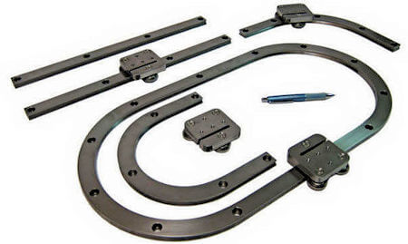
For applications where you don’t want to move in a straight line, we offer our curved rail linear guide products.
The rails are machined from carbon steel blanks, then surface heat treated to provide a hard wear resistant surface. Additional post treatment results in a satin black color appearance. Standard catalog products available now are straight, 90-degree turn, and 180 degree turn rail sections. These are standard off-the-shelf items for those who wish to build their own systems. CR40 Series Carriages are designed with three cam roller wheels for smooth movement.
For OEM applications we will make “custom” rail sections.
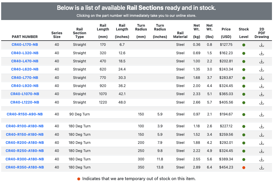
For many applications our standard catalog offering listed below will allow you to construct a complete system.
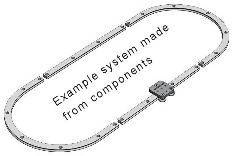
Below is a list of components required to make the example closed loop curved rail system in the sketch below.
Example Bill of Materials (BOM)
|
Part number
|
Description
|
Qty
|
|
CR40-L470-NB
|
Straight Rail Section, Length is 470 mm
|
2
|
|
CR40-R200-A180-NB |
180 Deg, 200 mm radius Turn Section
|
2
|
|
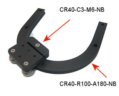
CR40-C3-M6-NB |
Carriage with M6 threaded holes
|
1
|
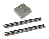
Rail sections for any of the straight or turn pieces can be “butt” join together to allow smooth transition of the carriage as it moves along the track.
To assist in making the best possible alignment on your end during installation, it is advisable to purchase an alignment tool.
It is important to also note that the base upon which you install the rail sections should machined flat and of good structural integrity.
CR40 Series Rail Section Features
- Black Color Satin Finish Appearance
- Heat Treated Surface Hardened Rails
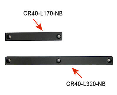
- Straight Rail Lengths up to 1220 mm (48 inches)
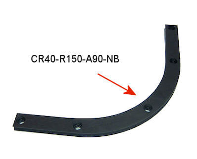
- 90 Degree Turn Sections with radius of 150 mm
- 180 Degree Turn Sections with radius as small as 100 mm
Typical Lead-time is 2-3 days
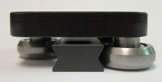
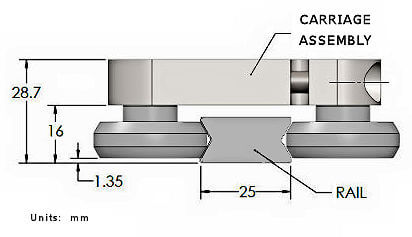
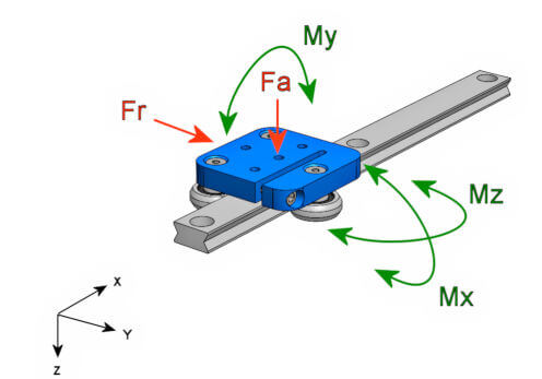
Carriage and Rail Assembly
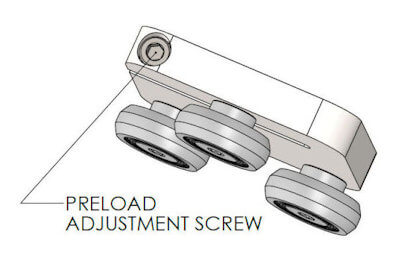
Carriage assembly is made of square shaped plate (12.7 mm thick) with three cam roller bearings attached. It is made of unhardened steel to allow for additional machining if customer wishes to add their own mounting holes.
Total height from bottom of rail to top of carriage is 28.7 mm.
Clearance between the bottom of the each cam roller to the bottom of the rail is approximately 1.3 mm.
For a system consisting of carriages and rails the typical lead-time is 2-3 days.
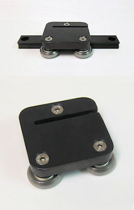
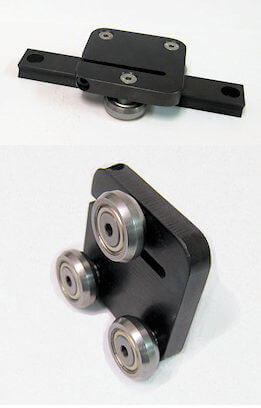
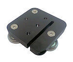
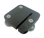
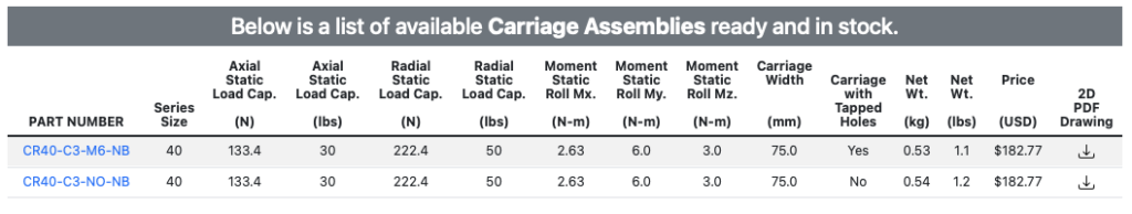
Below are some example part numbers with product pictures.
Lubricant Requirements
Applying a small amount of an NLGI #2 lithium-based grease with no solid additives such as MoS2 (molybdenum disulfide) along the surface where the cam roller wheel contacts the rail is recommended for quiet operation and long life.
Alignment Tool
Part number is CR40-ALIGNTOOL
Price is $50.00 each