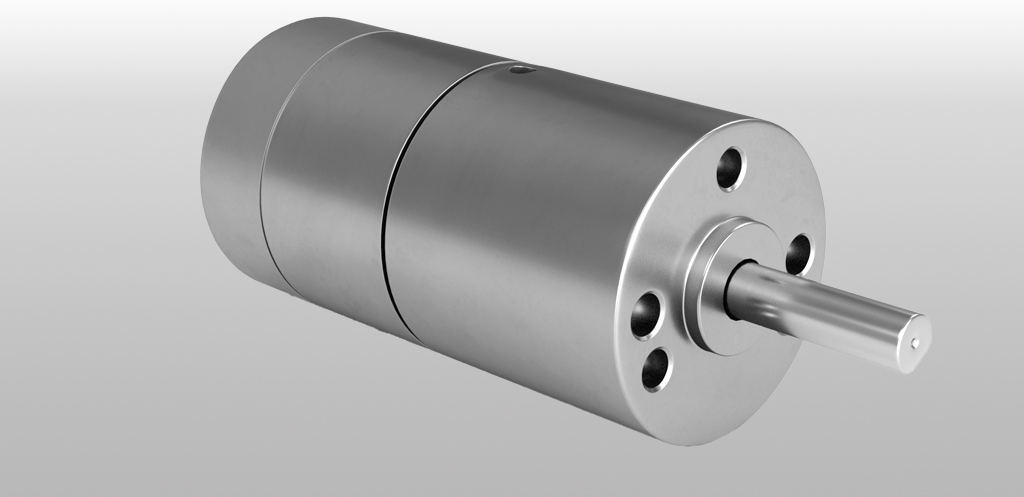
Rotary Piezo LEGS®, with direct drive and 30mNm torque output.
This is our smallest rotary Piezo LEGS®, with direct drive and 30mNm torque output.
Rotary Piezo Motor with built in encoder
- Rotary direct drive
- Built in encoder
- 30mNm torque output
- Self-locking
- No backlash
Piezo LEGS® LR17 Rotary Motor
This is our smallest rotary Piezo LEGS®, with direct drive and 30mNm torque output.
The i gives closed loop resolution of 0.2 mrad (0.01°), while open loop resolution is sub-microradian. Full force power-off locking is a safety function inherent to the design.
Not designed for vacuum and non-magnetic environments
Specifications LEGS® LR17
|
Type
|
Standard (A)
|
Unit
|
|
Diameter
|
17
|
mm
|
|
Angular range
|
360
|
°
|
|
Speed Range |
0-0-265 (0-44 rpm)
|
°/s
|
|
Step angle, full step
@ Delta, no load, 20°C |
1000
|
µrad
|
|
Motor resolution
14 bits, 8192 microsteps |
<1
|
µrad
|
|
Built in encoder
|
Yes
|
|
|
Encoder type
|
Magnetic, absolute
|
|
|
Encoder accuracy
|
2.0
|
mrad
|
|
Encoder resolution
|
0.2
|
mrad
|
|
Stall torque
|
0-15
|
mNm
|
|
Holding torque
|
>30
|
mNm
|
|
Recommended operating range
|
0-15
|
mNm
|
|
Vacuum
|
No
|
|
|
Operating voltage
|
42-48
|
V
|
|
Power consumption
|
3.5
|
mW/Hz
|
|
Shaft load, max
radial, 6.5 mm from mounting face |
1
|
N
|
|
Shaft load, max
axial |
2
|
N
|
|
Shaft press fit force, max
|
5
|
N
|
|
Mechanical size L x H x D
|
TBA
|
mm
|
|
Weight
|
30
|
g
|
|
Connector motor
|
CviLux CI1116M-2VD0
|
|
|
Material in motor housing
|
Aluminium, stainless steel
|
|
|
Operating temperature
|
-20 to +70
|
ºC
|
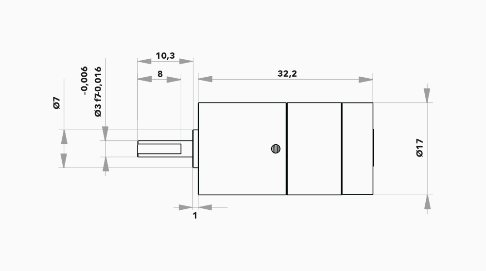
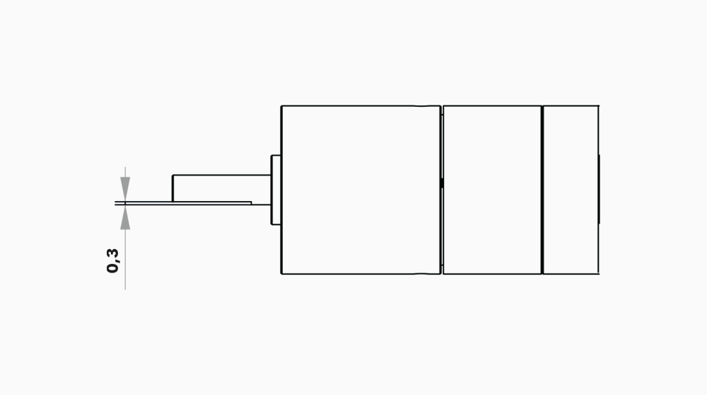
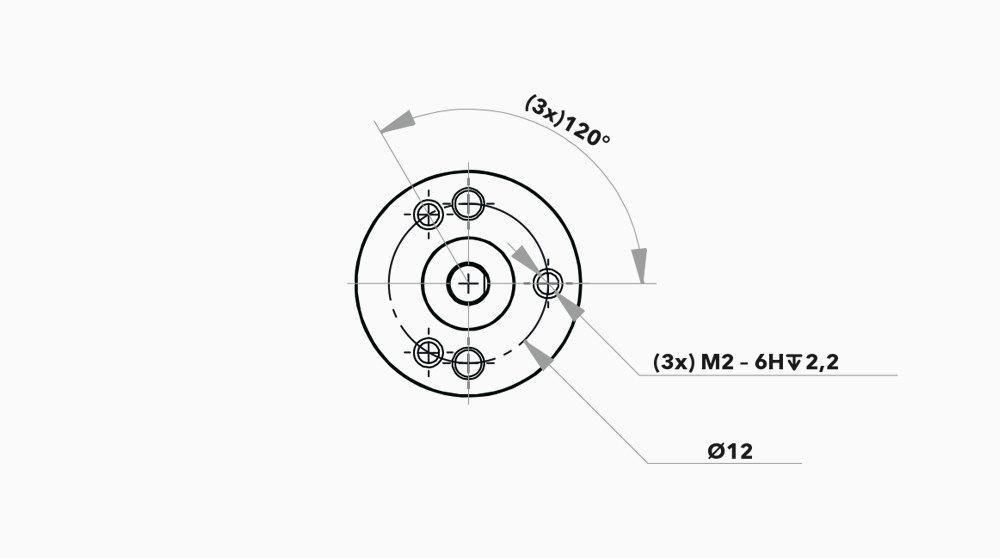
Main dimensions LR17
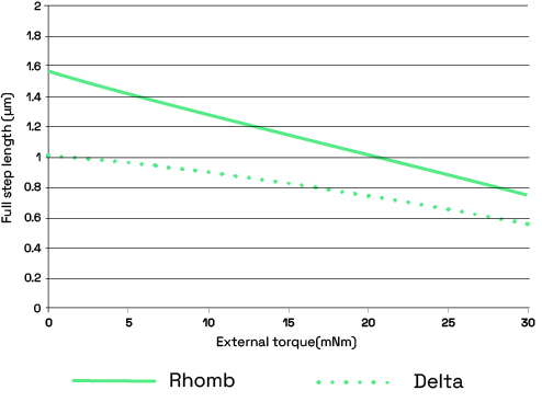
Motor performance LR17
Motor performance with waveform Rhomb (filled) and waveform Delta (dotted). The full step length is the average distance the drive rod moves when the legs take one full step (i.e. for one waveform cycle).
Note: A standard deviation σ of 0.5 μm should be taken into account.
Typical values are given for 20ºC.
Motor speed at 20 ºC no load
|
Waveform
|
Max feq. (Hz)
|
Speed range (mm/s)
|
|
Delta
|
3000
|
0–28 rpm (0–170°/s)
|
|
Rhomb |
0–44 rpm (0–265°/s)
|
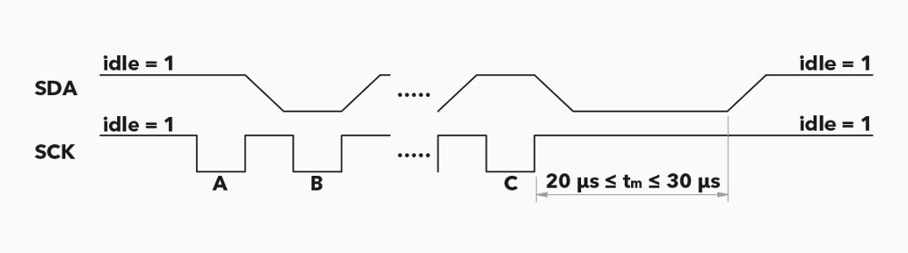
LR17 encoder information
The LR17 has an integrated magnetic absolute encoder. It gives 15-bit SSI data. SCK (Sensor Clock) and SDA (Sensor Data) are normally at high level (idle). When receiving a clock pulse from the controller, the LR17 will respond with position data. The SCK frequency should be 70–180 kHz. Data should be read shortly before the positive flank.
The time-out between positive flanks is 20–30 µs. The output data is 15 bits (msb first), followed by a stop bit. If SCK continues beyond the stop bit, there will be a second stop bit followed by repeated 15-bit data and a stop bit. A minimum of 120 µs is needed after position readout to make sure that position data is refreshed. Reading position every 0.5 ms is the maximum recommended rate for continuous operation.
A – 1st clock pulse, SDA stays idle until positive flank.
B – 2nd clock pulse, SDA output is bit1 (msb).
C – 16th clock pulse, SDA output is bit15 (lsb).
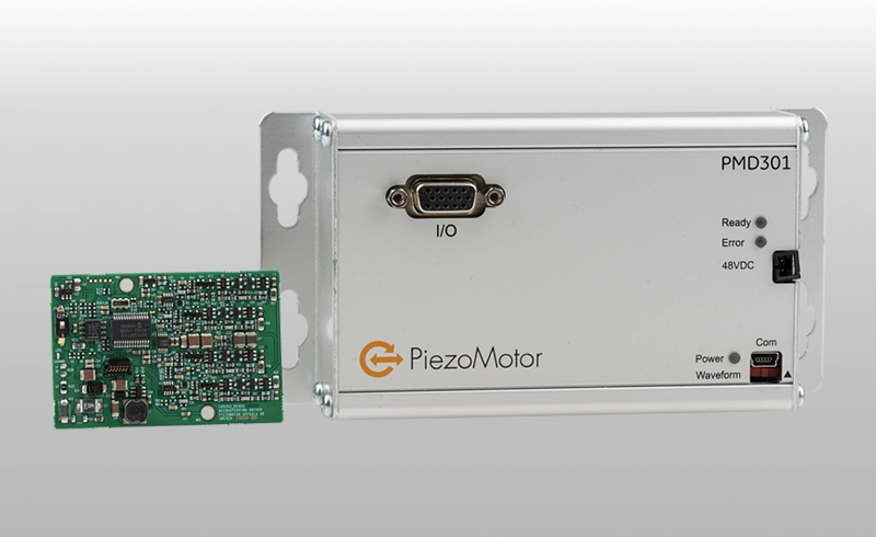
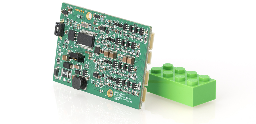
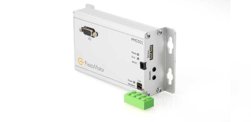
Controlling the motor
Our motor control units come in many different versions, with controllers and amplifiers for laboratory use as well as for integration into OEM devices.
We can also license the drivers for customers that want to build their own driver electronics.
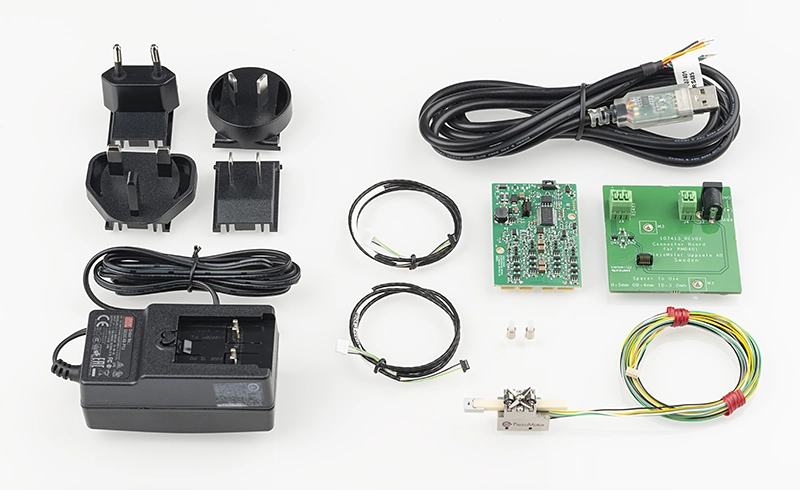
LR17 LEGS® Piezo Motor Starter Kit
Starter kits are available for the LR17. Starter Kits are for evaluation purposes only with a max quantity of 3 kits/customer. You only pay for the motor.