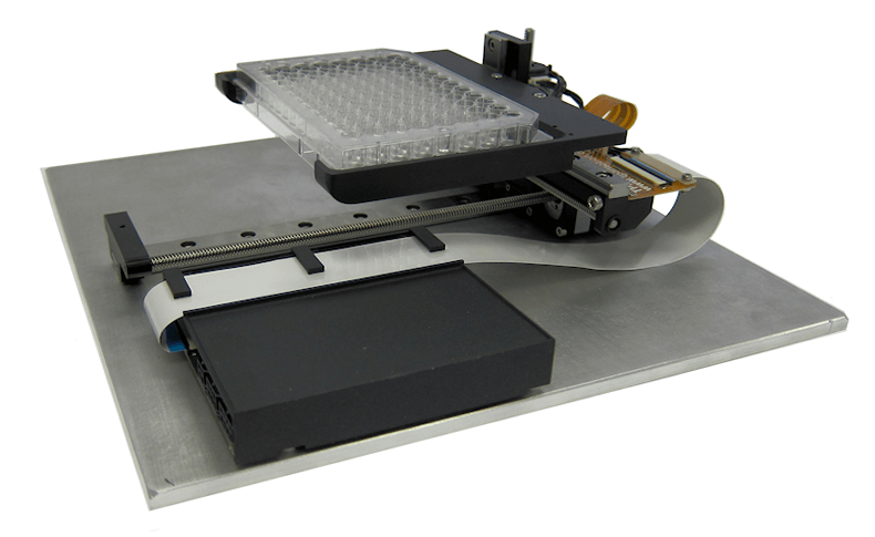
We make Microplate Robots for medical and scientific instruments.
We help Original Equipment Manufacturer’s (OEMs) rise above the competition with the best technology and the lowest cost.
Our microplate robots are fully featured XYZ motion systems for moving micro plates, glass slides or other payloads around inside your instrument. Each robot is highly integrated and optimized for size, enabling the most compact instrument possible. We have standard designs or we can work to your design specifications to meet your performance requirements. It is used in lab automation and automated liquid handling projects.
Featured below is our highly developed base model used in many desktop life science instruments today.
High Accuracy Screw Driven Microplate Handler
Performance
Our robot can carefully move a microplate and precisely position each well under your liquid dispensing tip or optical lens. Precision movement to the center of each well eliminates any chance of cross well contamination.
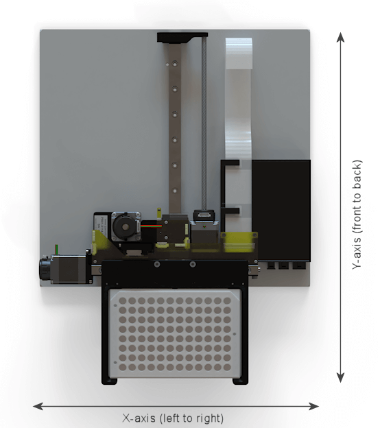
The design allows you to reach every well position while maintaining the smallest footprint within your instrument.
Footprint
|
Side to Side
|
215 mm
|
8.5 inches
|
|
Front to Back |
250 mm
|
9.8 inches
|
|
Height |
75 mm
|
2.9 inches
|
Travel or Stroke
|
X-axis
|
118 mm
|
4.6 inches
|
|
Y-axis |
168 mm
|
6.6 inches
|
|
Z-axis |
75 mm
|
1.4 inches
|
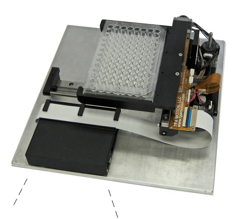
Pictures show XYZ microplate robot with drive and control board mounted to base plate.
Payload capacity is 250 grams (about 0.5 lbs).
Motors and Encoders
The robot uses 28 mm stepper (i.e., Nema 11) type motorized lead-screws to drive each axis. Each stepper motor includes an 800-line quadrature encoder. The lead-screws have a 2.54 mm lead (i.e., travel per revolution). This combination allows for very accurate positioning.
Downloads

Compact Assembly
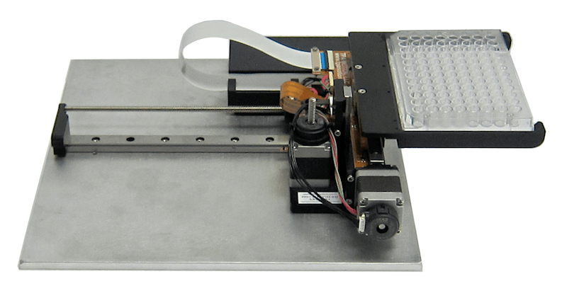
Miniature Linear Guides provide the structural support and allow almost frictionless motion along each axis.
Leadscrew Integrated Motors provide the driving mechanism.
These are just a few features that enable us to create a very compact design.
Very Low Profile Height – approximately 75 mm (2.9 inches)
Easy Robot Mounting
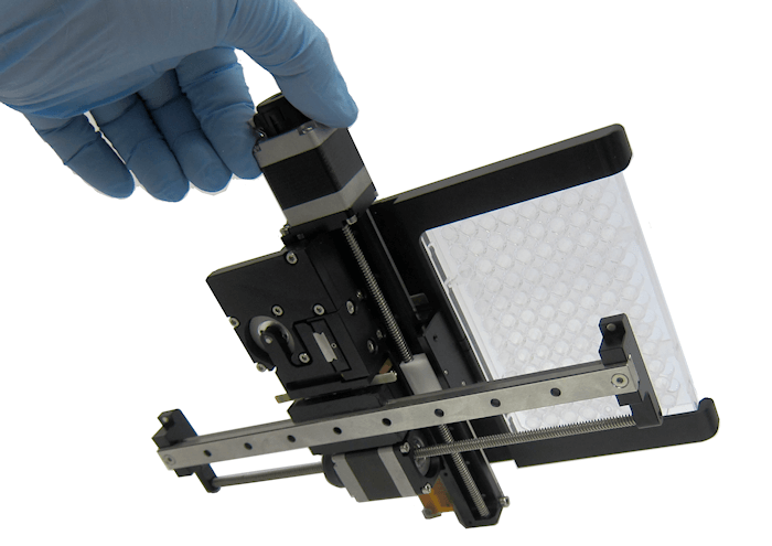
Installation is very straightforward. There are eight holes (see photo) in the linear guide rail for mounting to your instrument base. Any of two of the eight holes along the bottom linear guide rail can be used for mounting in most cases.
Each hole is spaced 25 mm apart and sized for M3 x 6 Socket Head Cap Screws.
Reference Position
Everything is referenced back to the linear guide so it is only important to align this component properly to your base or structure.
Compact Drive & Control Package
Fits neatly within the robot footprint.
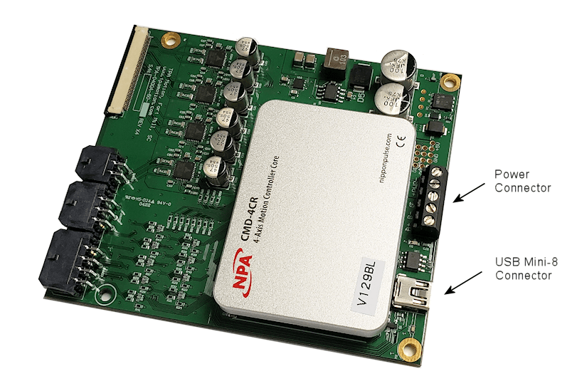
Each microplate robot is equipped with a compact drive and control package all on one printed circuit board. Four M3 x 8 screws are used to mount the PCB to the base.
A Flat Flexible Cable (FFC) is all that is required to transmit power and sensor data between the Controller and Robot.
Only power and USB connection are needed to be ready for operation.
4-Axis Motion Controller Data
Motion Control:
- Linear interpolation (two to four axis)
- Coordinated motion
- Absolute or incremental positioning
Programming:
- BASIC-like programming language (A-SCRIPT)
- Compile, read and write standalone programs
- Communication port: USB 2.0 and RS-485
Power:
- +24 VDC Power Input at 2-3 amps
Printed Circuit Board Size:
100 Length x 88 Width x 18 Height, Units: mm
Contact Us to discuss OEM Microplate Robot Designs
We can make custom OEM systems with high accuracy and precision for a wide range of microplates from 96 wells to 1536 wells to custom plate configurations.
Below is a short list of data we require to start a design process:
Envelope Size within which the robot must fit
Length of Travel for Each Axis
Travel Sensor Requirements
Accuracy Requirements
Type of Payload (i.e., micro plate) and weight
